There has been a lot of interest in solar charging and, honestly, we’re really interested too. Today we completed a prototype of a solar charging circuit. The results were VERY interesting.
We knew that there had to be a relationship between the voltage generated by a solar panel, the insolation (sun light hitting the panel), and the current drawn from the panel. Some research showed this to be absolutely true, and that it must be regulated. As shown in the figure below, every solar panel and amount of insolation result in a Current/Voltage relationship.

Solar Maximum Power Point (MPP)
As you pull more current, the voltage out of a solar panel can drop dramatically. For each size of solar panel there is a point in this relationship that results in the most power (Power = Current*Voltage) possible. This is know as the maximum power point, or MPP, of the solar panel. In order to stay at the MPP the current from the solar panel must be limited. This can be accomplished with the right circuitry.
Our prototype is based around a breakout board (that we made) of an SMD IC with features that make it capable of MPP tracking (MPPT). The results of this experiment can be seen in the photos below. In the photos a phone book was used to vary the amount of insolation on the solar panel. (I’m glad to know they’re still good for something. I threw it in the recycling bin as soon as I was done.) All of these pictures were taken in about 2 minutes. The only thing that changed was the position of the phone book.

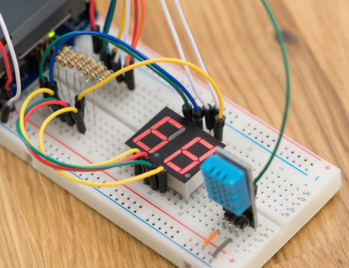
No insolation – Running on battery
In this picture the solar panel is completely covered and the project is running on battery power. The Fluke meter on the left is displaying the current flowing to the battery (hence is it negative when the battery is powering the project). The “project” for the demonstration is roughly 85 ohms of resistors putting a 45mA load on the battery. The ‘el cheapo’ meter on the right is displaying the voltage from the solar panel.

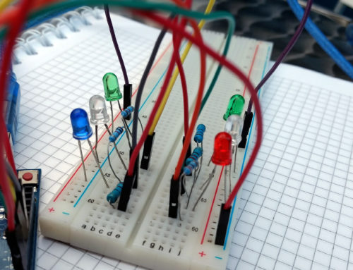
Partial insolation – Load supplemented by solar
Here the phone book is demonstrating a situation in which there is not enough insolation to power the project and charge the battery. However, the solar power does not go to waste. The power from the solar panel is supplementing the battery power. The current being drawn from the battery has been reduced from 45 mA to 33mA. While there is very little power being drawn from the solar panel, notice the voltage of the solar panel. The MPP of our solar panel is 17.5V. The IC monitors the voltage of the solar panel and reduces the current it draws if the voltage drops below a set point. This was set with the potentiometer on the breadboard to be ~17.5V, and the IC is doing a marvelous job at maintaining the voltage at this point.

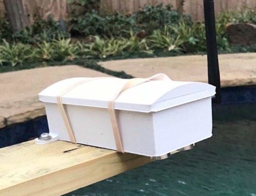
Full insolation – Project is powered by solar and the battery is charging
In this final picture there is full insolation on the solar panel. If you notice the current has changed directions. The solar panel is powering the project and charging the battery at 143mA. All of these transitions took place seamlessly and, regardless of the insolation, the solar panel is operating at MPP. In my opinion, this test was a wild success.
We are very excited about this technology. Whether or not we meet the stretch goal to include this in all of your energyShields, we are going to try our best to make this available for use with energyShields after the campaign has ended.
Notes: In this test, the Arduino is only being used for it’s voltage regulator.
We only have 24 hours remaining. You guys have been amazing backers and I’m excited to see what will happen tomorrow. Whether we end at $17,000 or $25,000 I consider this campaign to have been a great success.
Thank you for your continued support!
The NightShade Team
To support us on Kickstarter, please click the link below!
![]()
Leave A Comment
You must be logged in to post a comment.