Intro to Arduino: UART Serial Communication
One of the most basic communication protocols in electronics is the Universal Asynchronous Receive Transmit (UART) serial protocol. The UART protocol allows for two devices to communicate with each other. The protocol requires two wires between the devices that are communicating; one for each direction of communication. Each device has an independent transmit and receive module. These modules do not have to be in time with each other (i.e. asynchronous). When a device transmits, it sends data as a series (i.e. serially) of pulses. Each pulse represents one bit of data, so a byte (8 bits) of data is sent as eight pulses on the wire. These pulses are sent with a particular, predefined timing called a baud rate that must be understood by both devices.
Hardware
For two devices to communicate with UART serial, three wires have to connect them. The first two are communication wires. The transmit (TX) of the first has to connect to the receive (RX) of the second and the TX of the seconds to the RX of the first. The third wire is ground. The devices have to have a common ground reference, or the pulses may not be going from 0V to 5V. It might look like -5V to 0V, which would not register as pulses to the other device.
The TX and RX pins of an Arduino board are pins D0 and D1. They are labeled TX and RX, and they are connected to the UART-USB bridge of the Arduino board. This means that, when the board is connected to the computer through USB, the UART of the Arduino board is already wired to a virtual serial port on the computer (i.e. COM3). This allows the board to send and receive serial data with a serial terminal on the computer.
Arduino IDE
Setup
In order to use UART serial in the Arduino IDE, you have to initialize the serial module. The default setup only requires calling the Serial.begin() function. Serial.begin() requires that your desired baud rate be put into the function as an argument.
Serial.begin(9600); // Start the serial module with a baud rate of 9600 bps and the default configurationFor a more advanced setup, you can control the number of data bits sent per byte, parity, and the number of stop bits by adding a configuration argument to the Serial.begin() function. These parameters are explained in detail down in the Protocol section of this article. The default configuration is SERIAL_8N1, which is 8 bits of data with No parity and 1 stop bit. This configuration parameter can be changed to 5-8 data bits; No parity, Even parity, or Odd parity, and 1 or 2 stop bits.
Serial.begin(9600, SERIAL_6E2); // Start the serial module with a baud rate of 9600 bps, 6 data bits, even parity, and 2 stop bitsTransmitting
Serial.write()
This is the simplest output command. It sends only one byte of data at a time. A single value of 0-255. The input to the function can be defined with a numerical value or with a character in single quotes.
Serial.write(65); // Will transmit the value 65
Serial.write('A'); // Will transmit the value 65
Serial.print()
This command is built on the Serial.write() command. It is able to send many bytes, one after another, to form strings. This is most useful for transmitting messages (strings of characters). This input to this function can be a byte array, character array, or a string.
char array1[5] = {4, 8, 16, 23, 42};
Serial.print(array1); // Will transmit the values 4, 8, 16, 23, and 42

Serial.print("CAT"); // Will transmit the ASCII values for 'C', 'A', and 'T' (67, 65, 84)
Serial.println()
This is exactly the same as the Serial.print() command except that it adds a new line/carriage return character to the end of the string of bytes.
Serial.println("CAT"); // Will transmit the ASCII values for 'C', 'A', 'T', and newline (67, 65, 84, 13)Receiving
When we receive serial data in the Arduino IDE, we’re actually just reading data from a buffer. The Arduino environment takes care of grabbing every byte as it is received and placing it into this software buffer, which makes it that much easier for you to use. Here are the functions you might use when receiving data.
Serial.read()
Returns the first byte from the serial buffer. If no data is available, it will return -1.
int receivedByte;

receivedByte = Serial.read(); // Returns the first byte from the serial buffer
Serial.available()
Returns the number of bytes that are currently available in the serial buffer.
if (Serial.available() > 0) {
   receivedByte = Serial.read();
}
Serial.peak()
Returns the first byte in the serial buffer, but does not remove it. If no data is available, it will return -1.
Serial.flush()
Clears all bytes from the serial buffer.
Serial.parseInt()
Finds the next set of integers in the serial buffer and parses them together, outputting an integer value.
For more details on how to use these functions and to see a few more functions, visit the Serial reference page on Arduino’s website.
Example
Here is an example of using serial to print to the terminal. You will need to upload this sketch and then open the Arduino serial terminal and set the baud rate to 115200 bps to see the data transmitted from the Arduino board.
void setup() {
  Serial.begin(1152000); // Initialize serial with a baud rate of 115200 bps
}

void loop() {
  Serial.println(millis()/1000); // Print running time in seconds
  delay(1000); // Wait 1 second
}
Protocol
While the Arduino IDE has created a default setup, which will be the same on all Arduino devices, there are several protocol settings that can be changed in UART serial. It is important that all of the frame (format of a communication) settings match in both of the communicating devices.
Baud Rate
The rate at which individual bits of data are sent is called the baud rate. One of the most common baud rates for UART (the closest thing to default) is 9600 bits per second (bps). Other common baud rates are 300, 600, 1200, 2400, 4800, 19200, 38400, 57600, 74880, and 115200 bps. While these are common, it can be any rate that you choose to use as long as the hardware can handle it and both devices are programmed to use the same baud rate.
As I mentioned, hardware can limit the effective speed of communications. This is mainly due to the length of the wires of the UART transmission. You can easily run an Arduino board’s USB serial at 115200 bps because the actual length of the serial wires is from the Atmel MCU on the board to the USB-UART bridge IC on the same board. The rest of the communication to your computer is handled via USB, which is MUCH faster. If you are wiring two Arduino boards together with the TX and RX pins (UART) and long wires, you might need to slow the communication speed to ensure the integrity of the communications.
Data Frame
In the UART protocol, a byte of data is sent in a data frame or packet. A frame includes the data along with some other information to help make sure that the data is communicated accurately.
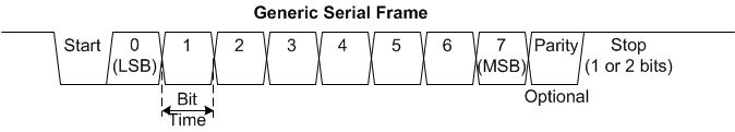
Start Bit
Every data frame begins with a start bit. This lets the receiving device know that data is about to be sent. There is always one start bit and it is signified as the idle data line (high) going low.
Data Block
The data block is sent immediately following the start bit. Most commonly, a full 8-bit byte is sent in every frame. However, you actually have to option of sending anywhere from 5-8 bits of data in the block. If all of the data you are transmitting only uses 7 bits of each byte, why waste time by sending a zero in every data frame?
Parity Bit
The parity bit is used for error checking the packet when it is received. There are two types of parity check; even and odd.
If we are using even parity, the number of 1’s in the data block are counted. If there is an odd number of 1’s in the data, the parity bit will be a one to create an even number of 1’s. If the number of 1’s in the data was already even, the parity bit would be a zero to maintain the even number.
When using odd parity, the coding is reversed. The 1’s in the data are counted and if the number is even the parity bit will be a one to make the total number odd. If the number of 1’s is already even, the parity bit will be a zero.
When the other device receives the data frame, it will count the number of 1’s in the data plus the parity bit to check that the odd or even parity is intact. If the parity is incorrect (i.e. even number when using odd parity), the receiving device knows that the data is corrupted. This simple method of error checking will catch if a bit was corrupted in the transmission. However, it cannot detect if an even number of bits (2, 4, etc.) were corrupted because the parity will be maintained.
Stop Bit(s)
The stop bit is the end of the packet. Most of the time only one stop bit is sent and it is signified as the line returning the high, idle state. However, you can choose to send two stop bits. This effectively reduces the overall speed of data transmission on the bus by adding another extraneous bit that has to be transmitted with every communication. This can be used to give slower devices a little more time to think between packets. There are also cases where the baud rate of a device can only be scaled by a factor of two and rather than completely halving the baud rate, you could add an extra stop bit in order to slow the data speed just enough to allow the slower device to keep up.
To learn more about Arduino UART Serial, visit the Arduino Serial Reference page.