Intro to Arduino: I2C Serial Communication
Inter-integrated Circuit serial communication, or I2C, is a two-wire serial interface (TWI) that was invented by Phillips Semiconductor (now NXP Semiconductors). It was designed for communication with lower-speed peripheral devices on the same board. The protocol is a master-slave protocol, where masters control the communication and the slaves only respond. The protocol allows for multiple master and multiple slaves, while it is more common to only have one master and multiple slaves.
Hardware
All of the devices on an I2C bus share the same Serial Data (SDA) line and the same Serial Clock (SCL). The I2C lines have to have a pull-up to Vcc because I2C devices operate with open-drain outputs. This means that their connection is either open (not connecting the wire to anything) or draining (connecting the line to ground). The open-drain output is not able to drive the line to a high voltage so, a pull-up is provided to pull the line high when it is released (open state). These pull-up resistors are usually 4.7kΩ, but they can be anywhere from 2.2kΩ to 10kΩ depending on the needs of the system.
In the Arduino IDE
The Wire library for Arduino is used to perform I2C/TWI communication. Here we will look at some basic examples of using the Arduino as the bus master to write to and read from a slave device with the address 0x55 (85). You will have to include the Wire library into your sketch to use these functions. (Click Sketch -> Include Library -> Wire)
Setup
To initialize the Wire library, you will have to call the Wire.begin() function. This is usually placed in the setup() area of your sketch.
Writing to the Slave
To write a register on a slave device, you have to initiate communication with the device (slave address), write the address of the register that you wish to write, and then write the value that you wish the register to be.
Wire.beginTransmission(85); // Begin communication with slave address 85 (0x55)
Wire.write(12); // Write the register address that we want to target
Wire.write(42); // Write the value that we want in register 12
Wire.endTransmission(); // Send the stop condition and end the transaction
Reading from the Slave
In order to read a register from the slave device, we begin by initiating communication with the slave, writing the register address to the pointer register, and sending a restart condition. Then, a read is performed, reading the desired number of bytes from the slave address.
Wire.beginTransmission(85); // Begin communication with slave address 85 (0x55)
Wire.write(12); // Write the register address that we want to target
Wire.endTransmission(FALSE); // Send the restart condition

Wire.requestFrom(85, 1); // Perform read request from slave address 85 and read 1 byte from the register that it is pointed at (12)
receivedByte = Wire.read(); // Read the byte that was received
Reading and Writing Multiple Bytes
The I2C protocol allows for multiple bytes to be written or read in one transaction. This is accomplished by having the address register on the slave increment with each byte sent or received. The transaction begins by writing the first (lowest value) register address that you want to read/write. Then, as the bytes are read/written the address register will increment the target address.
// Write 3 bytes to registers 12, 13, and 14
Wire.beginTransmission(85); // Begin communication with slave address 85 (0x55)
Wire.write(12); // Write the register address that we want to target.
Wire.write(42); // Write the value that we want in register 12
Wire.write(23); // Write the value that we want in register 13
Wire.write(14); // Write the value that we want in register 14
Wire.endTransmission(); // Send the stop condition and end the transaction

// Read 3 bytes from registers 12, 13, and 14
Wire.beginTransmission(85); // Start communication with slave address 85
Wire.write(12); // Write pointer register to 12
Wire.endTransmission(FALSE); // Send restart condition

Wire.requestFrom(85, 3); // Read 3 byte from slave address 85, starting at register 12
receivedByte1 = Wire.read(); // Read byte from register 12
receivedByte1 = Wire.read(); // Read byte from register 13
receivedByte1 = Wire.read(); // Read byte from register 14
Visit Arduino’s reference page to learn more about using the Arduino Wire library.
Protocol
In the I2C protocol, all of the communication is controlled by a master. Slave devices have memory registers that can be written or read by a master and each slave device has a unique address. Every communication begins with a start condition, followed by the address of the slave that the master is targeting.
Note: In all of the protocol diagrams, any action that is bold and underlined is performed by the slave device.
Slave Addresses
You will see three different length I2C addresses used in documentation; 7-bit, 8-bit, and 10-bit.
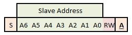
7-bit Addresses
This is the standard length I2C address. The 7-bit address is transmitted immediately after the start condition and it is immediately followed by the read/write (RW) bit. The RW bit indicates whether the master is writing to the slave (0) or reading from the slave (1).
8-bit Addresses
When you see an 8-bit address, you should see two addresses listed for the same device; one for reading and one for writing. This is truly an inappropriate way to list I2C addresses because they are just taking the real 7-bit address of the slave and adding the read/write bit on to the end of it. The real address is the upper 7 bits.
10-bit Addresses
The standard 7-bit address system of I2C only allows for 127 unique addresses. In order to expand the number of available device addresses, a method was created to use 10-bit addresses. This system was designed to be compatible with 7-bit addresses so that you can use both 7-bit addressed devices and 10-bit addressed devices.
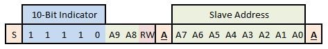
The first byte sent by the master, which is usually the only address byte, begins with a 10-bit address identifier. This the sequence 11110 is never used on the front of a 7-bit address, so this first byte will never match a 7-bit slave address. After the 10-bit identifier, the first two bits of the address are sent, followed by the read/write bit. The second byte contains the rest of the 10-bit address. These two bytes will replace the address byte of a 7-bit device in any of the transactions.
Write Slave Register (1 Byte)
When the master is writing a register to a slave device, it follows this protocol:
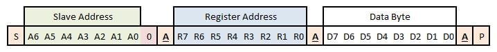
A write operation begins with the start condition, generated by the master. This is followed by the 7-bit address and a 0, to indicate that the master will be writing to the slave. After the address and RW bit, the slave will send an acknowledge. Then the master will send the address of the register that it wishes to write. Again, the slave will send an acknowledge. Finally, the master will send the byte that is to be written to the register on the slave. The slave will acknowledge and then the master sends the stop condition to indicate that the transaction is complete.
Read Slave Register (1 Byte)
Reading a register on a slave device is slightly more complicated. The process requires two steps. In the first step, the master writes the address of the register to be read. The communication is then restarted and the master initiates a read command. The slave then begins sending data from the address that was written to the slave in the first step.

The read transaction begins exactly like the write transaction. The master sends the slave address with the write bit and the slave acknowledges. Then the master writes the register address that it wishes to read and the slave acknowledges. Then the master starts a new transaction by sends a stop condition and a start condition, or by sending a restart. The difference is that the master maintains control of the bus when it performs a restart, while it may lose control of the bus if it stops and then tries to start. This is not an issue on single master buses. The new transaction begins with the master sending the slave address with the read bit. The slave acknowledges and then begins to send the byte located at the register address that the master wrote previously. Once the slave finishes transmitting the whole byte (8 bits) the master does not acknowledge (NA) and sends the stop condition to indicate that the transaction is complete.
Writing or Reading Multiple Bytes
Writing or reading multiple bytes with the I2C protocol is quite natural. When the master writes a register address to the slave, the address is stored in a pointer register that tells the slave where to read or write next. After the slave performs a read or write operation to that memory location, the slave increments the address in the pointer register the next memory address. Now, the master can continue by reading or writing another byte, rather than issuing a stop condition.
Sometimes, it is critical to read multiple registers at one time. In certain cases, a single, large (multi-byte) value can be stored across several byte addresses in the slave. To make sure that all of the bytes are read together (representing the register value at the same point in time) all of the bytes that make of one value are locked during a read operation. This is a common occurrence in devices like a real-time clock (RTC) because some of the values are so large that they require more than one byte and the values are constantly changing.
Multi-Byte Write

A multi-byte write is exactly the same as a single byte right up to the point where the slave acknowledges the transmission of the data byte. Normally, after the slave acknowledges the transmission, the master would send a stop condition. Instead, the master proceeds to transmit a seconds byte. This byte will write to the next register in the memory of the slave. In this manner, this master can continue writing successive bytes into the slave’s memory. Once the master has finished write, it then sends the stop condition to end the transaction.
Multi-Byte Read

The multi-byte read is also exactly like the single byte read up to the end of the first byte transmitted. When reading a single byte, the master would not acknowledge (NA) the transmission of the first byte, which tells the slave to stop transmitting. Instead, in a multi-byte read, the master acknowledges (A) the byte transmitted and the slave proceeds to transmit the value of the next memory address. The master continues acknowledging the transmitted bytes as long as it wants the slave to continue transmitting. When the master has received the last byte that it wants, it completes the transaction by not acknowledging and then sending the stop condition.