What are Microcontrollers, and How Do I Use Them?
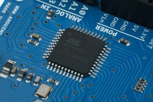
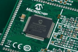
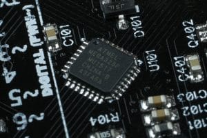
Microcontroller units (MCUs) are small systems on a chip (SOC) that include a computer processor, memory to store instructions (program code) and data, and I/O peripherals for communication, measurement, and control. The user writes program code which is then compiled into machine code and loaded into the microcontroller. The microcontrollers behavior is determined by these instructions. Microcontrollers can read the digital state of connections, create digital output (turn an output pin to high voltage, low voltage, or disconnected), communicate with other devices (serial, SPI, TWI, parallel, etc.), measure analog voltages, perform mathematical operations, and do most anything a programmer can imagine.
Types of Microcontrollers
There are many microcontrollers available today. While their features widely vary, all microcontrollers accomplish the same basic goal of computing and interfacing with other circuitry. Some of the more common brands on microcontrollers include Texas Instruments, Microchip, STMicroelectronics, and Atmel (which was recently purchased by Microchip). The most significant difference between different microcontrollers is the peripherals. Let’s take a look at some of the different peripherals you might be interested in.
Digital Inputs and Outputs (I/Os)
The most basic interface of a microcontroller is a digital input and output (Digital I/O). When choosing a microcontroller, you can choose how many digital I/Os you would like. This corresponds to the number of connections (pins) that can be read digitally or switched as an output.
Using as an Input
What do we mean when we say read a pin digitally? Digital simply means that there are only two options; yes or no, on or off, 1 or 0. As we all know, there’s really nothing digital about electricity. In a 5V circuit, you will see 5V and 0v, but you may also see 4.97V, 4.63V, 0.23V, 1.27V, etc. The way we accomplish digital circuitry is by defining what we mean by a 1 or 0. Typically, we’re going to use the middle of the voltage range as the turning point between logic 1 and 0. In a 5V micro controller, if a voltage is above 2.5V it is a 1 and if it is lower than 2.5V it is a 0. So, reading a pin digitally just means that we check to see if the voltage of the pin is high or low (above or below Vcc/2). This is very useful for reading things like buttons or switches.
Using as an Output
When we use a pin as an output, things are a little simpler. If we set the output state of a pin to 1 (true), that pin will be connected to high-voltage (5V in a 5V microcontroller). If we set the output state to 0 (false), that pin will be connected to ground. Something we have to wrap our head around is that current can flow through these pins in either state. If you connect a pin to an LED (with a resistor) to ground, the LED will light up with the output is high, because current will flow from high voltage to ground. If the pin is set low (0), current will not flow and the LED will turn off. Contrary to this, you can wire an LED (with resistor) from 5V to the microcontroller. Now we get the opposite behavior. When the pin is set high, no current will flow, because current will not flow from 5V to 5V. But if the set the pin low, current will flow from 5V, through the LED (and resistor), to the microcontroller lighting the LED.
High Impedance State
Digital I/Os actually have a third state as well. We can set our output pin back to an input, even if we don’t intend to read it. When an I/O pin is set as an input it a very high impedance (resistance). This prevents current from flowing into or out of the microcontroller, essentially isolation it from the circuit. The is very important if we want to stop interfering with the circuit.
Analog-to-Digital Converters (ADCs)
An ADC peripheral enables microcontrollers to read analog voltages. The ADC lets us read an input voltage in relation to Vcc and ground. When picking an ADC we have to choose its resolution. The resolution of an ADC is measured in bits. An 8-bit ADC reads the full range of voltage in 28 – 1 or 255 increments. A 10-bit ADC will measure the voltage range in 2810 – 1 or 1023 increments. The higher the resolution of the ADC, the more accurately we can measure the voltage.
When we talk about the full voltage range of the ADC, what we mean is the range between the ADC’s low-voltage reference and its high-voltage reference. These references can be changed with settings. Usually, the low-voltage reference is ground, but it isn’t always. The high-voltage reference is often the operating voltage of the microcontroller, but it can also be a fixed internal reference voltage or an external reference voltage.
Calculating the Resolution
When you are using the ADC, it will read the voltage on the pin and return the value that corresponds to its place between the ADC’s references. The equation below demonstates this.
\(\large \text{ADC Result} = \frac{V_{meas} – V_{ref, low}}{V_{ref, high} – V_{ref, low}} \times (2^\text{(Bits of Resolution)} – 1)\)
Often, this number output from an ADC is not nearly as useful to us as actually knowing the voltage. The voltage can be retrieved from the ADC value by using the reverse calculation, shown here.
\(\large V_{meas} = (V_{ref,high} – V_{ref,low}) \times \frac{\text{ADC Result}}{2^\text{(Bits of Resolution)} – 1} + V_{ref,low}\)
Something that we always need to consider is the resolution of the ADC. The resolution of the ADC is the smallest difference in voltage that it can detect. When the ADC returns a result, the actual voltage could be as much as a half increment in either direction.
\(\large V_{error} = \pm \frac{1}{2} \times \frac{V_{ref,high} – V_{ref,low}}{2^\text{(Bits of Resolution)} – 1}\)
Reading an Analog Voltage with an ADC
In this example we’ll assume that we’re reading an analog voltage from a potentiometer. The ADC has a 8-bit resolution and is using the microcontroller’s operating voltage of 5V as the high reference and the low reference is ground. When ever the low reference is ground (0V) the equations reduce significantly.
\(\large \text{ADC Result} = \frac{V_{meas}}{V_{ref, high}} \times (2^\text{(Bits of Resolution)} – 1)\)
\(\large V_{meas} = V_{ref,high} \times \frac{\text{ADC Result}}{2^\text{(Bits of Resolution)} – 1}\)
After we have initiated the read function, the ADC returns the value 214. Now we can use the seconds equation to calculate the voltage that corresponds with that value.
\(\large V_{meas} = 5.00V \times \frac{214}{2^{8} – 1} = 5.00V \times \frac{859}{255} = 4.20V\)
To fully understand our reading, we also need to calculate the error of this reading. That equation is also simplified when the low reference is 0V (ground).
\(\large V_{error} = \pm \frac{1}{2} \times \frac{V_{ref,high}}{2^\text{Bits of Resolution} – 1} = \pm \frac{1}{2} \times \frac{5.00V}{2^{8} – 1} = \pm 0.0098V\)
Taking the error into account, our actual answer is 4.20V ± 0.01V.
Digital-to-Analog Converters (DACs)
A DAC is exactly the opposite of an ADC. You load the DAC with the digital representation of the voltage within the DAC’s reference range, and it outputs the corresponding voltage to the best of its precision.
Calculating the Resolution
Just like ADCs, DACs have a resolution given in bits and use reference voltages. The equations for a DAC are listed below.
\(\large \text{DAC Value} = \frac{V_{DAC} – V_{ref,low}}{V_{ref,high} – V_{ref,low}} \times (2^\text{Bits of Resolution} – 1)\)
\(\large V_{DAC} = \frac{\text{DAC Value}}{2^\text{Bits of Resolution} – 1} \times (V_{ref,high} – V_{ref,low}) + V_{ref,low}\)
Communication
Most microcontrollers offer hardware communication modules, which are very helpful. First, let’s briefly discuss the protocols and then we’ll talk about why the modules are handy.
Serial Communication
Digital devices communicate data with one another using many different protocols. Many protocols are serial, meaning that they send bits of data one at a time on the same wire, while other protocols are parallel, sending more than one bit at the same time (parallel).
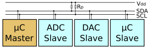
Some examples of serial communication would include Universal Asynchronous Receiver/Transmitter (UART), oneWire, two-wire interface (TWI), serial peripheral interface (SPI). All of these protocols send bytes (8-bits) of data one bit at a time, one after another, on the same wire. Some of these have a dedicated wire for each direction of communication, while others share the same lines for both directions.
Parallel Communication
Parallel communications are becoming less and less common as communication speeds increase. This seems counter intuitive because it would seem that sending all 8 bits of a byte at one time would be faster than sending them one at a time. However, today’s devices operate so quickly that the time it takes for the electricity to carry across the communication line can be longer than the time between different data being sent. This means that timing is very important. So, if you try to send 8 pieces of data side-by-side, you have to make sure that they all arrive at exactly the same time. Because of this, the speed has to be limited to ensure data integrity. While parallel communication is less common, it is still used. One of the most common places I encounter it is in LCD screens.
Software vs. Hardware Communication
All of these protocols can be generated using digital I/O pins and software, but sometimes you will want your processor to keep doing other things, instead of spending a lot of time banging out a message on the wires. While our communication protocols are quite fast, microcontrollers can do things much faster, so it wastes a lot of their time to sit and wait for each bit.
To remove this load from the processor, most microcontrollers include hardware modules that handle the communication protocols. This allows the processor to hand the data that needs to be sent to the hardware module and go think about something else while the data is tediously sent over the wires.
Other Modules
Computational Co-Processor
In order to relieve stress on the main processor of a microcontroller, sometimes computational co-processors are implemented. These co-processors are generally designed to handle heavy math calculations. This allows the main processor to be thinking about other operations while math operations are handled elsewhere.
Real Time Counter
Some microcontrollers include a Real Time Counter (RTC). This module is a separate circuit within the microcontroller that very precisely counts a separate crystal (usually running at 32.768kHz), which allows the accurate tracking of time passes. This makes it possible to implement an accurate clock using the microcontroller.
Logic Modules
Sometimes microcontrollers will include logic circuitry between pins, allowing the microcontroller to check the relationship between two pins without looking at both and comparing them in software. This can help to speed up processing time in things like a high-speed control loop.
These modules are circuitry that connects to two external pins, creates the result of the desired logic (AND, OR, NOR, XOR, etc.) and connects the result to the processors’ input in place of the pin connection. Now, reading the state of one input actually reads the relationship between two pins.
Try It Yourself!
Our wonderful circuit simulator is not very useful when it comes to the experience of using a microcontroller. I recommend that, if you are interested, you buy an Arduino compatible board and start experimenting. When you jump into using a microcontroller there are a handful of things that have to be set up (correctly) to get it to do anything. (Clock source, clock scaling, peripheral enables, etc.) The Arduino organization has done a wonderful job at creating an environment that lets you program a microcontroller without having to deal with these details. It provides you a ready-to-use general purpose setup. Now, beginners and experts alike can jump in and quickly create results with their microcontroller.* Once you get your Arduino board, check out our Arduino tutorials to get started right away!
*If you try to do something very advanced in Arduino, you may find that the general purpose setup they have created will not suit your needs. In this case, you need to be using a more powerful programming environment like Atmel Studio.


