What are Inductors, and How Do I Use Them?
An inductor is an electrical device that stores energy and resists changes in current flow. This ability to store energy and resist current is measured in a unit called inductance.
As current flows through an inductor, a magnetic field builds inside the component. The magnetic field consists of stored energy that will be released again as the current diminishes. This can be imaged like charging a battery, but instead of charging the battery to a certain voltage, you charge the inductor to a certain amount of current.
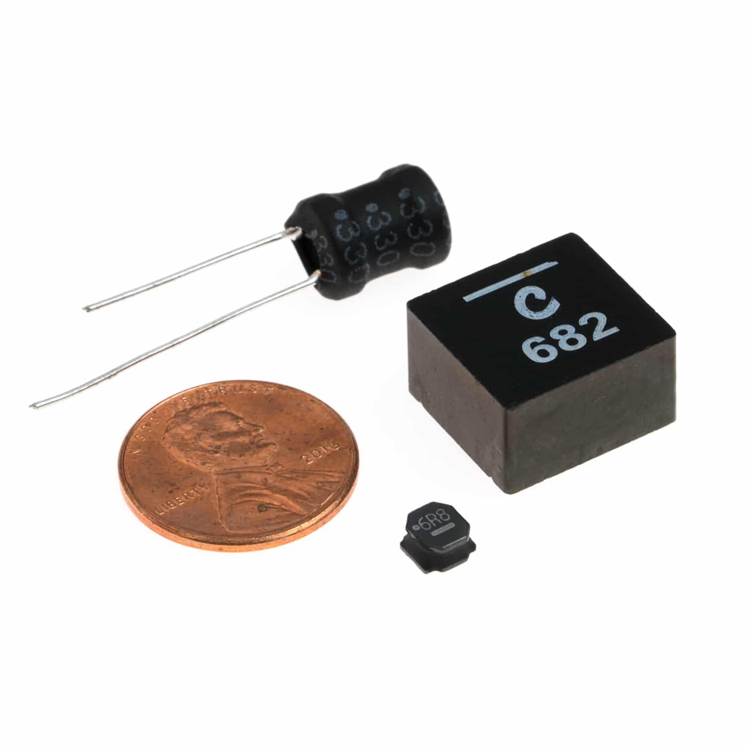
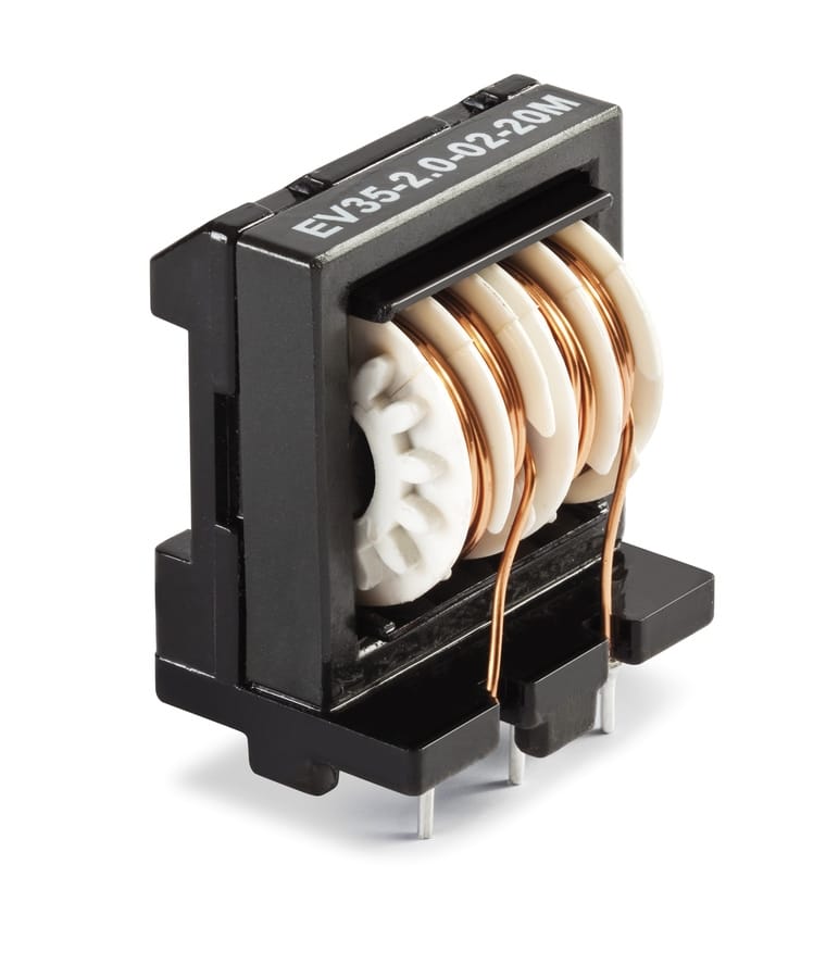
Inductors are generally made by a wrapping wire around a core material. The diameter of the wire dictates how much current the inductor can handle, the length of the wire relates to the amount of inductance, and the core material acts as a multiplier for inductance. Different core materials, such as iron or ferrite, help increase inductance while carrying heat away from the coiled wire.
How Do I Use an Inductor?
The first rule of an inductor is that the amount of current flowing through an inductor cannot change instantaneously. If you disconnect an inductor while current is flowing through it, the voltage out of the inductor will instantly jump as high as it must in order to create a spark from the wire you just disconnected, so that the current keeps flowing momentarily. This property makes inductors excellent for power filtering circuits. They are also commonly used in oscillating circuitry, and switching power regulators.
Oscillating Circuits
Inductors can be used to make circuits with a resonant frequency. These circuits include the well known LC and RLC circuits. A resonant frequency is the frequency at with a circuit will respond most to an input. This is also the frequency that a circuit will settle at when oscillating on its own.
LC Circuit
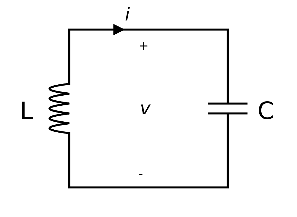
An ideal LC circuit, like the one pictured below, will have a resonant frequency governed by the equations below. This first equation will return the frequency in Radians/second, the second will return cycles/second, otherwise known as Hz.
\(\large \omega_{0} = \frac{1}{\sqrt{LC}}\)
\(\large f_{0} = \frac{1}{2\pi \sqrt{LC}}\)
RLC Circuit
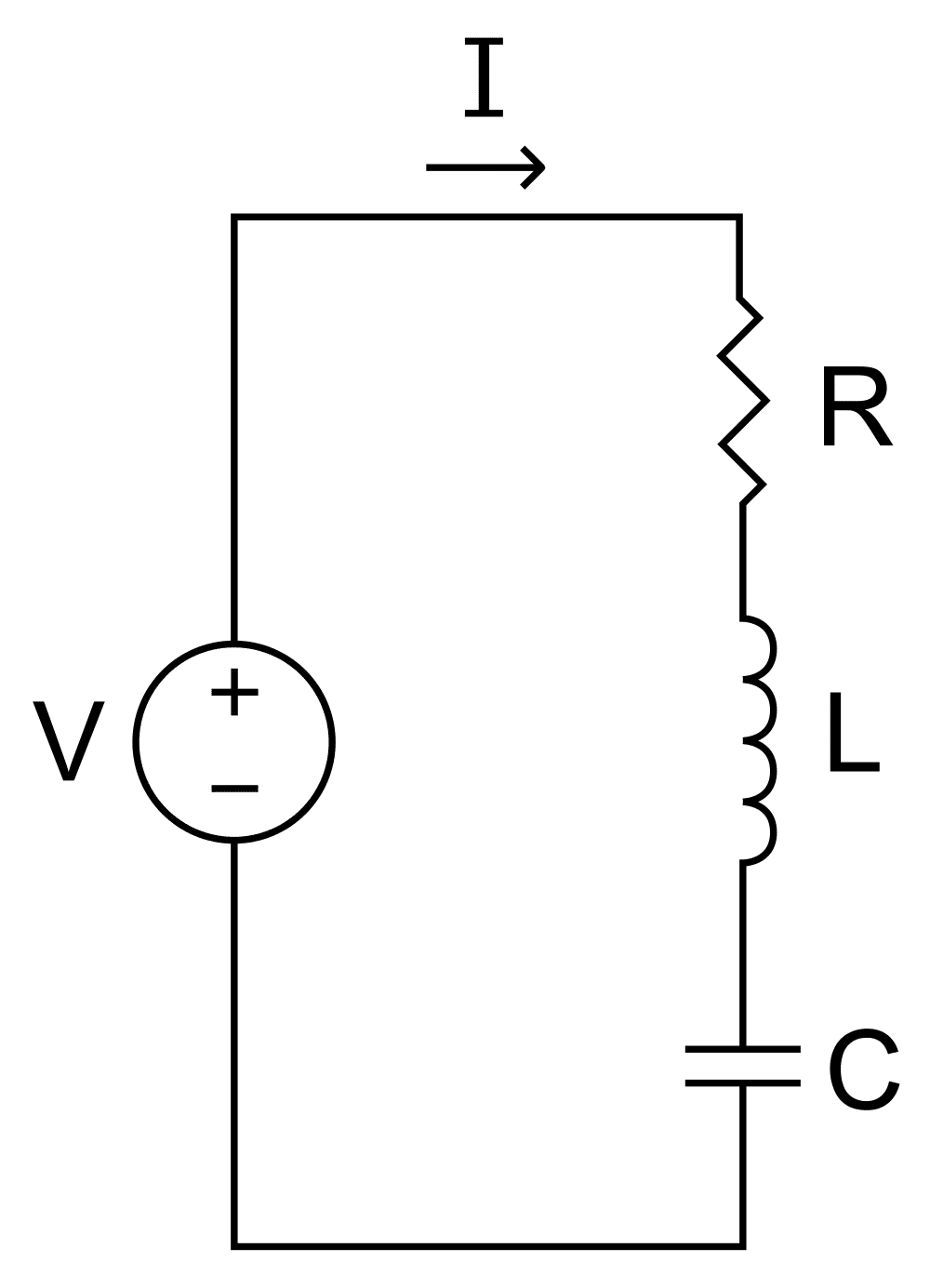
In reality, all circuits have resistance. That is where the RLC circuit comes into play. Below is a circuit diagram of the RLC circuit. The resonant frequency of the RLC is the same as the LC circuit, but the resistor of the LRC adds a damping factor to the circuit.
\(\large \omega_{0} = \frac{1}{\sqrt{LC}}\)
\(\large f_{0} = \frac{1}{2\pi \sqrt{LC}}\)
\(\large \zeta_{N} = \frac{R}{2}\sqrt{\frac{L}{C}}\)
Filter Circuits
Inductors can be used to make excellent power filtering circuit. These filters can filter out low frequency (high-pass), high frequency (low-pass), certain frequencies (band-stop), or all but some frequencies (band-pass). You can read about the different types of filter circuits on Wikipedia’s LRC Circuits page.
Switching Regulators
Inductors also let us switch between voltage levels with very low power losses, using circuits like a buck converter or boost converter. You can follow these links to their Wikipedia pages to learn more.
Try It Yourself!
Below are examples of a buck converter and boost converter circuits. In the real world, we use a buck or boost IC that contains a lot of control circuitry to properly regulate and maintain the output voltage of the circuit. In these examples, the circuit is operating with fixed parameters (frequency, duty cycle, etc.) just to illustrate the how the circuits work.
The buck converter is the simpler of the two circuits here. The purpose of a buck converter (a.k.a. step-down converter) it to efficiently reduce voltage. While linear regulators use transistors to convert excess voltage into heat (wasting energy), a buck converter reduces the voltage by only turning the power on for a percentage of the time (pulsing) and smoothing the pulses into an “average” lower voltage. A high voltage square wave is pulsed into an inductor. Current starts to flow through the inductor while the input power is on. When the input power is switched off, the energy previously stored in the inductor flows out, continuing the flow of power even though the input is turned off. In this case, the pulsed power is being filtered by the inductor (and capacitor) into an average of the input pulses. When the input power is switched on, the current flows from the source, through the inductor, to the load (resistor in this case), to ground, and back to the source. When the input power is switched off, the energy that was stored in the inductor flows out to the load, to ground, and then through the diode back to the inductor. It is crucial that the circuit is completed even when the input is switched off (hence the diode).
The purpose of a boost converter (a.k.a. step-up converter) is to create an output voltage that is higher than the input voltage. The buck converter works on the principle that current MUST keep flowing through an inductor, no matter how the voltages around the inductor change. In the boost converter, the input voltage is connected directly to the inductor. Then the output of the inductor is connected to ground to start current flowing through the inductor. Then the output of the inductor is disconnected from ground. Even when disconnected, the current through the inductor must keep flowing through the inductor, so it takes the only path available; through the diode to the higher voltage at the output. This process moves small packets of power from low voltage to high voltage.