Electrical Hookup
This is a guide on how to make connections using the Trēo system. At a minimum, you will need the following:
- Development Board (ie. Arduino, Raspberry Pi)
- Trēo™ Adapter
- Trēo™ Module(s)
- Trēo™ Cable(s)
Adapter Installation
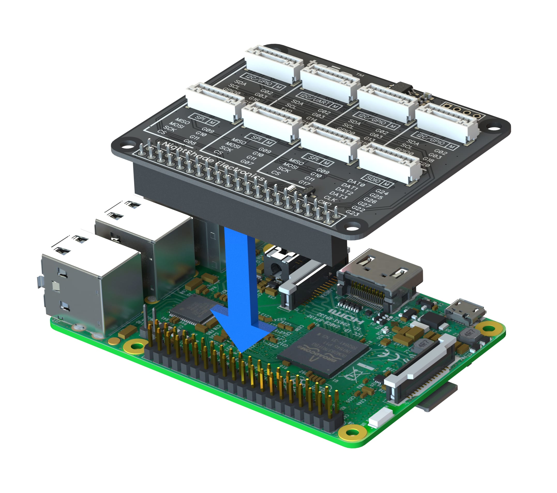
Trēo adapters are designed for a particular development board, such as Arduino and Raspberry Pi. Connect the Trēo adapter to the corresponding development board by aligning the headers of the adapter to the headers of the development board and pressing down until the headers are fully engaged.
Module and Cabling Installation
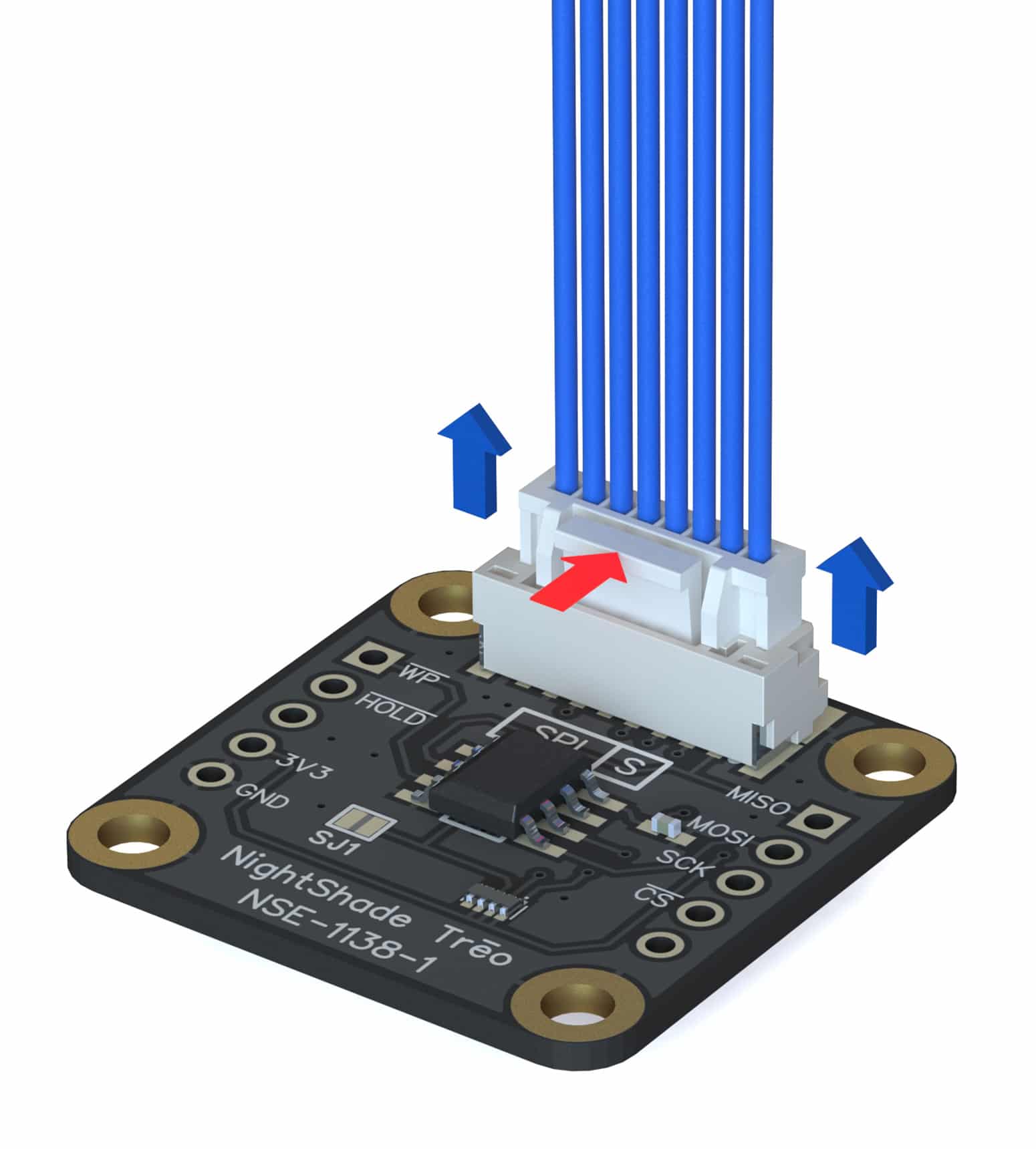
Trēo cables are used to connect Trēo modules to any Trēo adapter regardless of which development board they are connected to. There is one type of cable used to connect all Trēo modules, so you only need to choose the appropriate cable length for your project. The connectors are keyed such that you cannot insert them the wrong way. To connect, align the plug to the receptacle and lightly press until you hear a click. To disconnect, press the locking lever (shown by the red arrow below) and pull from the white connector. Do not pull on the wires.

Module and Adapter Connections
Even though the cables can connect to any receptacle in the Trēo system, the modules will only function properly if the following relations are held:
- Connect an S to an M.
- Connect to the same protocol.
- Check current draw.
These relations are explained more in the sections below.
M/S Designation
The M/S designation stands for an electrical Master/Slave operation. The items marked with “M” control the items marked with “S”. Each module or adapter will list the M/S designation near the receptacle like in the picture below. It is more likely that the adapters will be masters and the modules will be slaves.

Protocol Designation
For any slave module to function, the connected master adapter or module needs to have at least the protocol of the slave module listed. For example, an I2C/UART master can provide for either an I2C, UART, or I2C/UART module. But, an I2C master can only provide for an I2C slave module, not for UART or I2C/UART. Other protocols that Trēo supports are GPIO, SPI, and SDIO. Each module or adapter will list the protocol near the receptacle like the picture in the above section.
Current Draw
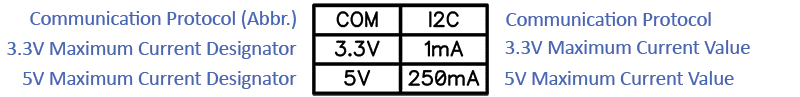
Trēo adapters contain many receptacles that can connect to modules. However, adapters have a maximum current draw capacity for each voltage level which is listed on the adapter. Before running power through the Trēo system, ensure that the total current being drawn by the modules does not exceed the current capacity of the adapters for each voltage level. Every module will have a table that resembles the picture below.
\(\Large I_{Module1, 3.3V}+I_{Module2, 3.3V}+…\leq I_{Adapter, 3.3V}\)
\(\Large I_{Module1, 5V}+I_{Module2, 5V}+…\leq I_{Adapter, 5V}\)
Module and Adapter Connections Example
Here is an example to show how we can connect the 512kb EEPROM Module (NSE-1138-1) and the 4 Character 7-Seg Display (NSE-1157-1) to a Raspberry Pi Adapter (NSE-1121-1).
512kb EEPROM Module (NSE-1138-1)
The SPI protocol and slave designation are boxed in blue below. The maximum current draw of 2mA at 3.3V is boxed in red below.


4 Character 7-Seg Display (NSE-1157-1)
The I2C protocol and slave designation are boxed in green below. The maximum current draw of 1mA at 3.3V and 250mA at 5V is boxed in red.

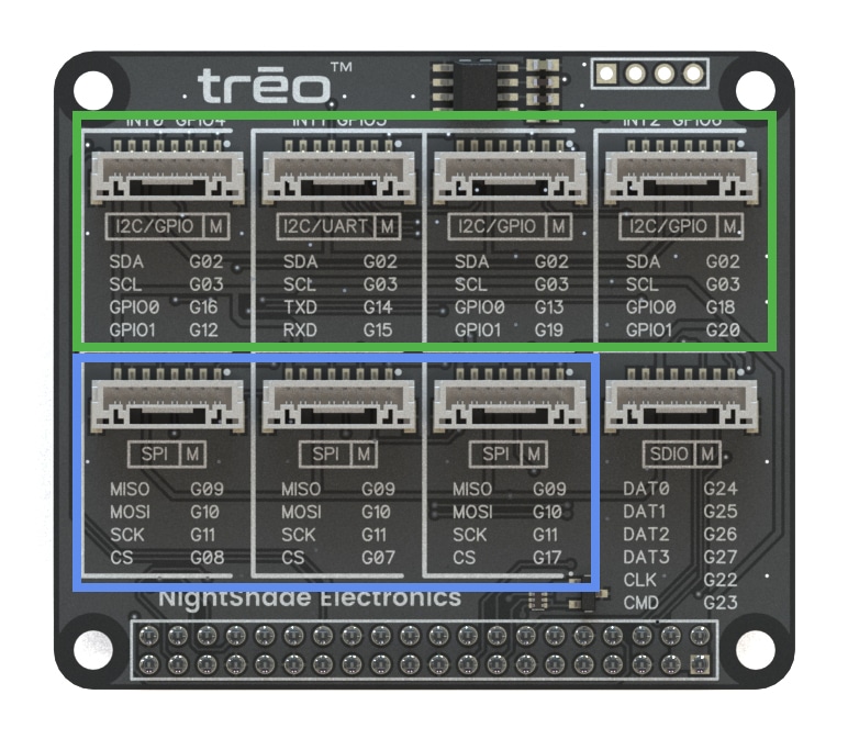
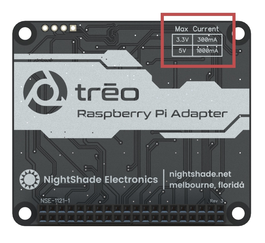
Raspberry Pi Adapter (NSE-1121-1)
The master connectors that the 512kb EEPROM module (SPI/S) can connect to are boxed in blue in the picture below. The master connectors that the 4 Character 7-Seg Display slave module (I2C/S) can connect to are boxed in green below. Note that some of the master connectors below are also designed to support GPIO or UART. The maximum current capacity for each voltage level is boxed in red in the picture below. The calculation for if the two modules can connect to this adapter is shown in the example calculation below.
Current Draw Calculation
In looking at the pictures from the sections above, the EEPROM module lists a maximum current draw of 2mA at 3.3V. The display module lists a maximum current draw of 1mA at 3.3V and 250mA at 5V. The adapter lists a maximum current capacity of 300mA at 3.3V and 1000mA at 5V.
Comparing the current draw to current capacity for 3.3V:
\(\Large 2mA+1mA\leq 300mA\)Comparing the current draw to current capacity for 5V:
\(\Large 0mA+250mA\leq 1000mA\)
The above equations are true, so the current draws are within the acceptable range.
We are successfully able to connect the 512kb EEPROM Module and the 4 Character 7-Seg Display to a Raspberry Pi Adapter!