Electrical Specification
All Trēo modules have a standardized electrical interface that enables one type of cable to be used between any Trēo module and any Trēo Adapter. The Trēo Adapters translate these connections to the platform specific interface of the development platform (Arduino, Raspberry Pi, etc.).
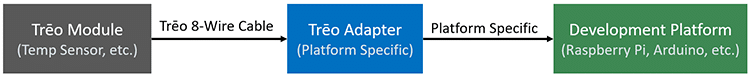
To enable the connection of any module to any adapter, a standard 8-wire interface was designed to carry signals, power, and interrupts. Depending on the protocol needed, the usage of the 8 wires may vary, but the physical cable is always the same.
Pin Assignments
The assignment of power pins (5V, 3.3V, GND), data pins (D0-D4), and a hardware interrupt line (INT) are consistent among all the modules per the table to the right. In the rare case that a protocol requires more than four data lines, the 5V power pin and hardware interrupt pin are switched to data lines.
| Pin # | Data | SData |
| 1 | D0 | D0 |
| 2 | D1 | D1 |
| 3 | D2 | D2 |
| 4 | D3 | D3 |
| 5 | INT | D4 |
| 6 | 3.3V | 3.3V |
| 7 | GND | GND |
| 8 | 5V | D5 |
Protocol
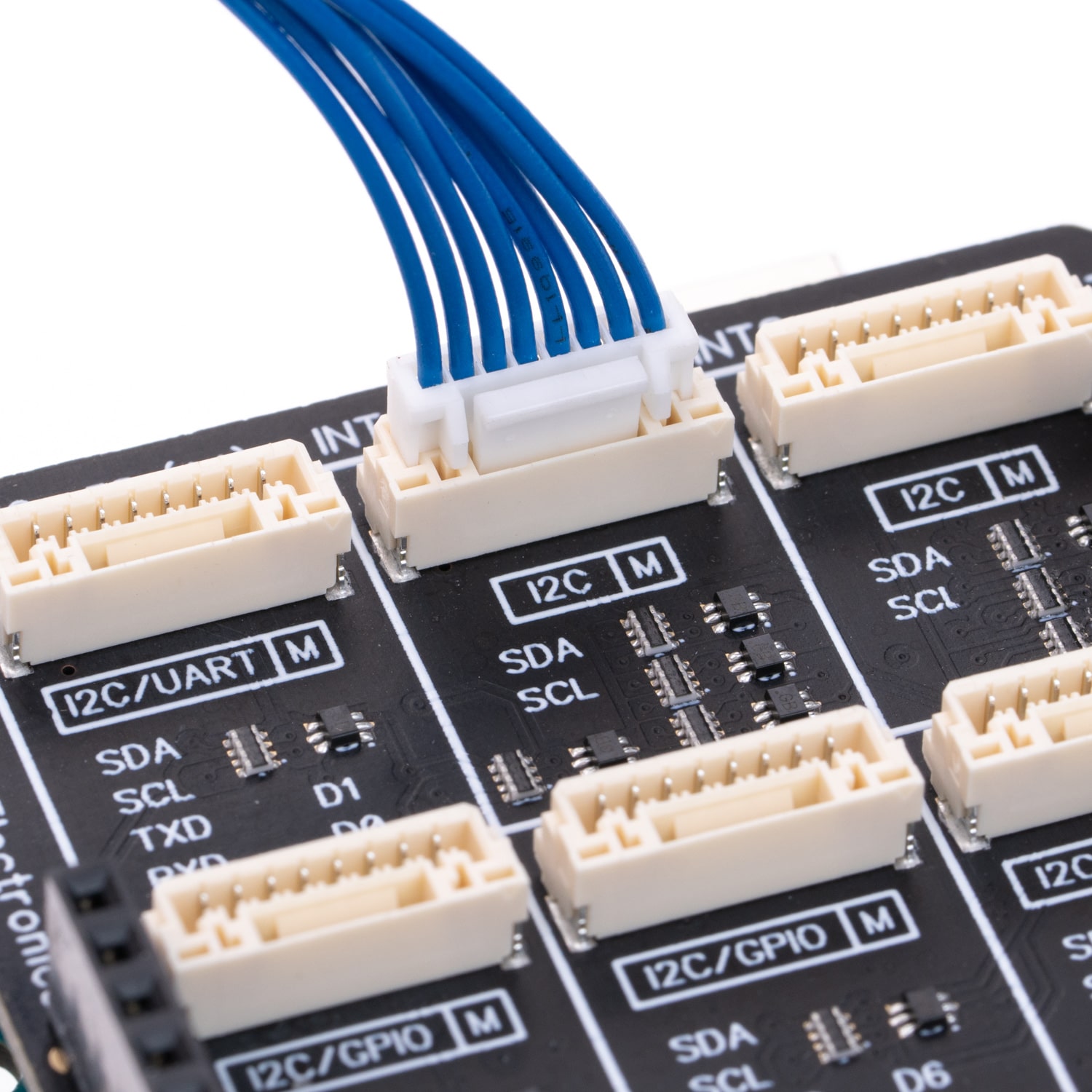
The protocol on the cable varies depending on the specific module. For example, the user can use the cable to connect any Trēo I2C slave module to any other Trēo I2C master device (e.g. Trēo Adapter Board on an Arduino). The protocol and whether the item is meant to be used as a slave or master is marked near the Trēo connector on each of our products as shown in the picture on the right. The Trēo 8-wire specification currently supports I2C, GPIO, UART, SPI, and SDIO protocols. The table below shows how the data lines are used for each protocol on each pin.
| Protocol | D0 | D1 | D2 | D3 | D4 | D5 |
| Pin # | 1 | 2 | 3 | 4 | 5 | 8 |
| I2C/GPIO | SDA | SCL | GPIO0 | GPIO1 | INT | |
| I2C/UART | SDA | SCL | TX | RX | INT | |
| SPI | MISO | MOSI | SCK | CS | INT | |
| SDIO | DAT0 | DAT1 | DAT2 | DAT3 | CLK | CMD |
Signal Levels
Certain rules are followed to standardize signal levels to protect hardware and ensure interoperability of Trēo hardware. See below for an overview of these rules.
All Data Signals
All data lines are standardized to operate at 3.3V. In cases where hardware operates at 5V (e.g. Arduino Uno), level shifters are integrated into the adapter or module to normalize the signals to 3.3V before they enter the cable. They are designed to sink up to 4mA and source up to 10uA.
GPIO Signals
All Trēo GPIO signals (e.g. buttons, switches, LEDs) are active low. Microprocessors are generally better at sinking current than sourcing it. This makes them operate better at active low than active high. In the case of a button (an input) the GPIO signal is pulled to the logic high state (3.3V) by default using a pull up resistor. When the button is depressed, it connects the signal line to logic low (ground) alerting the host processor of an active state. In the case of an LED (an output), the LED will be off while the GPIO signal is in a logic high state and on when the signal is in a logic low state.
Interupt Signals
All interupt signals on Trēo modules are active low and, therefore, pulled to the logic high state by default. For more details, see the Using Hardware Interrupts (Advanced) page.