Hardware Reference – energyShield 2 Basic
Hardware Overview
Pin Descriptions
| Pin Name | Description |
|---|---|
| 5V | Normally connected to the 5V regulator. Can be disconnected by cutting “5V:5V” solder jumper. |
| 3.3V | Always connected to 3.3V regulator. |
| GND | Always connected to ground net. |
| Vin | Normally disconnected. Allows user to connect 5V regulator to Vin pin. This is needed for certain boards (pcDuino, Intel Galileo, ect.). Can be connected with 5V:Vin solder jumper. |
| RAW | This pin provides unregulated power from the battery that does not switch off. It also has a higher maximum current than the regulated pins. It is useful for powering parts of a project that need power even when the shield is switched off (example, an LCD screen). |
| EN | This pin allows the shield to be turned on without using the switch. Connect this pin to the RAW pin will activate the power outputs while the switch is in the OFF position. (1 kΩ Input) |
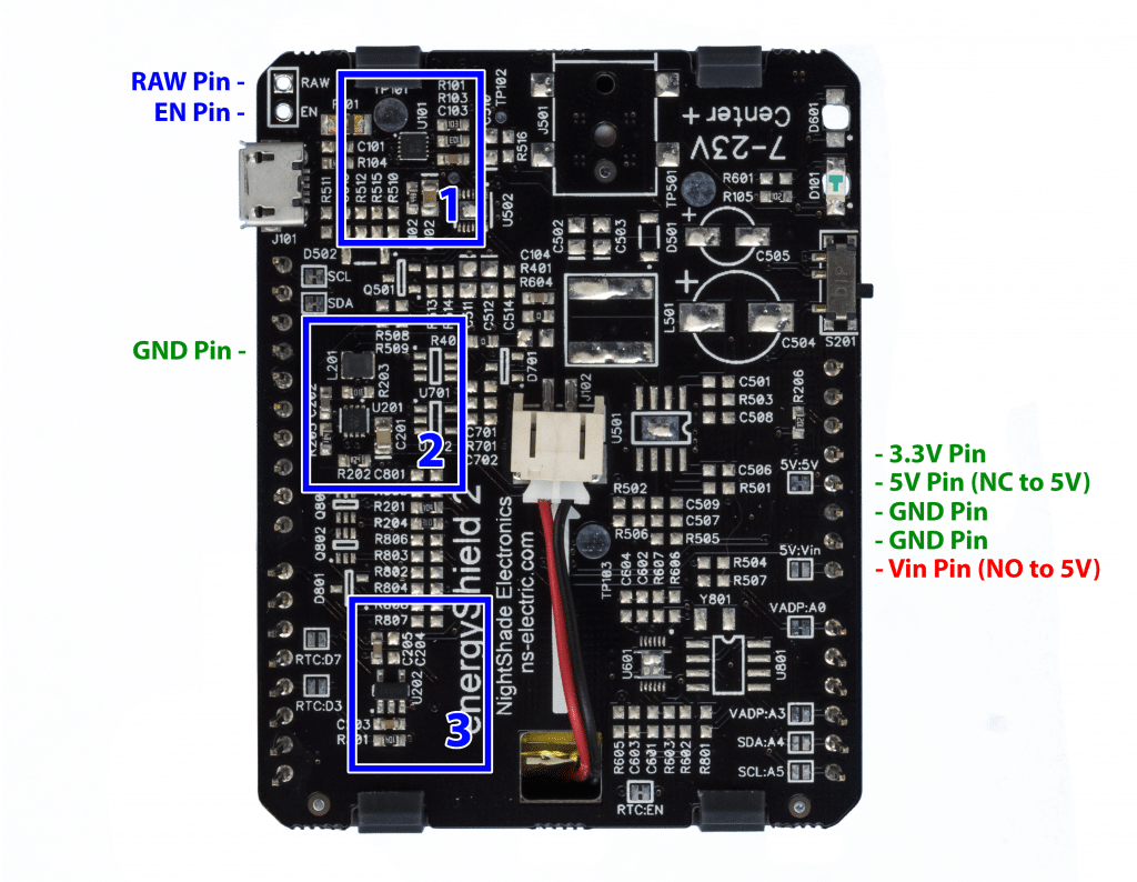
All other pins on the energyShield 2 Basic are not connected. They serve as pass-throughs for the Arduino Headers.
Circuit Descriptions
| Circuit Number/RefDes (Noted with blue boxes) | Description |
|---|---|
| 1 / U101 | USB Charger. This IC controls the USB charging of the LiPo battery. |
| 2 / U201 | 5V Boost Switching Regulator |
| 3 / U202 | 3.3V Linear Regulator |
Power Pin Specifications
| Description | Specification |
|---|---|
| USB Input Voltage | 5V |
| USB Input Current | 500mA Max |
| 5V Output Current | 1000mA Max |
| 3.3V Output Current | 300mA Max |
| RAW Pin Output Voltage | 3V – 4.2V (Battery Voltage) |
| RAW Pin Output Current | 1800mA Max |
Logic Level Pin Specifications
| Description | Specification |
|---|---|
| EN (Enable Pin) Logic Threshold | 1.5V |
| EN (Enable Pin) Voltage Tolerance | 0 – 5V |
Power Flow Chart
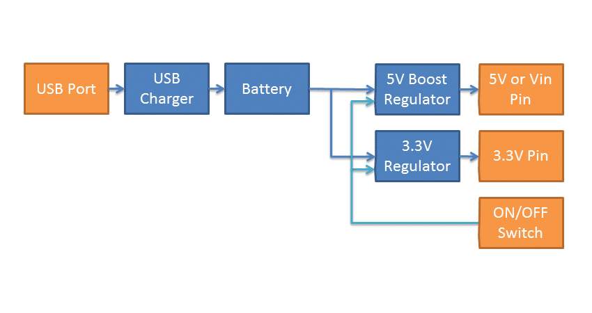
This flow chart illustrates how power is handled in the energyShield 2 Basic.

