What are Voltage Regulators, and How Do I Use Them?
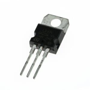
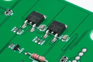
Voltage regulators are circuits (often Integrated Circuits or ICs) that maintain a constant output voltage level. Voltage regulators, of some kind, are used in many of the electronic devices around us. This is why many of them can accept a range of input voltages or use one input voltage to run all parts of its circuitry. For example, microwave use 110VAC to run the magnetron but needs a lower DC voltage for the microcontroller that operates the buttons and screen. It does this by regulating the 110VAC to the DC voltage required for each of these devices. In this article, we will focus on DC voltage regulators.
Types of Voltage Regulators
There are two common types of DC voltage regulators; linear and switching. Each has their strengths and weaknesses. Below we will try to explain some of these differences.
Linear Voltage Regulators
Linear regulators are based on a transistors linear region of operation. They are able to reduce the input voltage by choking down the flow of power and burning the excess voltage as heat. The current passes through a transistor (typically a BJT) that is being opened by a control circuit based on the output voltage. If the output voltage is too low, it opens the transistor more. If it is too high, it closes the transistor a little more. As the transistor resists the flow of electricity, it gets hot. Because of the inefficient nature of linear regulators, it is best to only use them for small differences in voltage. Despite their inefficiencies, linear regulators are very accurate and quick to respond to changes in load. The efficiency of a linear regulator is equal to the ratio of the output voltage to the input voltage and the power consumed in the regulator is equal to the voltage difference from input to output times the current.
\(\large \epsilon_{linear} = \frac{V_{out}}{V_{in}} \times 100\% \text{, } \quad P_{linear} = (V_{in} – V_{out}) \times I\)
Here you can see why you want to keep the voltage difference across a linear regulator as small as possible.
Efficiency of a Linear Regulator
If we regulate 24V down to 5V with a linear regulator, our conversion efficiency will be 21%.
\(\large \epsilon_{linear} = \frac{5V}{24V} \times 100\% = 20.8\%\)Similarly, if we used a linear regulator to regulate a lithium ion battery’s nominal voltage of 3.7V down to 3.3V, our nominal efficiency over the whole battery voltage range would be 89%.
\(\large \epsilon_{linear} = \frac{3.3V}{3.7V} \times 100\% = 89.2\%\)As we can see, linear regulators are actually quite efficient when used with a small voltage difference, but terribly inefficient with large differences. We also need to remember that more important than efficiency, is the amount of power we’re actually loosing in the regulator. If we’re drawing a 10A load from our lithium ion battery being regulated to 3.3V, we will be burning 40W of power! That is a lot of heat! Likewise, if we’re only drawing only 5mA at 5V regulated from 24V we are only losing 95mW, which is tolerable in most applications.
\(\large P_{\text{5V, 5mA}} = (24V – 5V) \times 0.005A = 0.095W\)\(\large P_{\text{3.3V, 10A}} = (3.7V – 3.3V) \times 10A = 40W\)
Switching Regulators
Switching regulators regulate power in small “packets” of energy.
A step-down (buck) regulator turns the power on and off very quickly and then smooths its out to create an average of the switched power. This averaged output will inherently be a lower voltage than the input power because the input was only on for a percentage of the time.
A step-up (boost) converter pushes the packets of energy from a lower input voltage to a higher output voltage. This pushing/pumping is achieved with the use of inductors or capacitors.
Both of these types of regulators can have efficiencies greater than 90%, regardless of the size of the voltage difference. The downsides to switching regulators are that they are much more complicated than linear regulators and their voltage regulation is not as accurate.
An Ideal Solution
Sometimes, when voltage must be stepped down very far and the output voltage has to be very accurate, both a switching and a linear regulator will be used. The switching regulator is used to efficiently regulate the voltage most of the way down. Then the power is run through a linear regulator to reduce it the last bit and tightly regulate the output voltage.
Using a Buck Regulator and a Linear Regulator
In this case, we are going to discuss running a 1A load at 5V from a 24V source and the voltage needs to be very well regulated. Because of our need for very accurate regulation, we should use a linear regulator, but this is going to lead to very high losses. Let’s take a look at the efficiency and power loss of using a linear regulator.
\(\large \epsilon_{linear} = \frac{5V}{24V} = 20.8\%\)\(\large P_{loss} = (24V – 5V) \times 1A = 19W\)19W is a lot of power to throw away, especially when our load only needs 5W. (P = V x I = 5V x 1A) Now, let’s consider using a step-down regulator to do most of the work and then finish it with the tight linear regulation. Something we have to take into consideration is that linear regulators need a certain amount of overhead voltage to work with. These days, most can work with less than 1V of overhead, so that’s what we’ll give it. The switching regulator will step the voltage from 24V to 6V and then the linear regulator will go from 6V to 5V. We’re also going to assume that our step-down regulator is operating with 90% efficiency.
\(\large \epsilon_{combined} = \epsilon_{switching} \times \epsilon_{linear} = 90\% \times \frac{5V}{6V} = 75\%\)\(\large P_{total} = \frac{P_{load}}{\epsilon_{combined}} = \frac{5W}{75\%} = 6.67W\)\(\large P_{loss} = P_{total} – P_{load} = 6.67W – 5W = 1.67W\)In this case, we only lose 1.67W of power! We just reduced the total power consumption by more than 72%!
How Do I Use A Voltage Regulator
Well, that is an epic question for this article. Using a voltage regulator is entirely dependent on the regulator’s circuit. You will need to check the IC’s datasheet to answer this one. A general rule would be to put a capacitor before the input of the regulator and also put one at the output. This will help to reduce voltage ripple. Also, you can add a couple of different size capacitors in both places to increase the range of noise that will be filtered out.
Try It Yourself!
In this example, you can see very simple linear and switching step-down regulator circuits. Normally, both of these circuits would have complicated controller circuitry to make them more accurate, but they were omitted for this example to make them easier to understand.
The linear regulator uses an NPN BJT to regulate the voltage. An NPN BJT opens more as more current flows from the base to the emitter. In this regulator, a Zener diode is used to maintain 5.6V on the base of the transistor. As the output voltage falls the tiniest bit below 5V (5.6 – transistor drop of 0.6V), more current flows from the base through the transistor letting more current through the collector. This provides very quick regulation of the output voltage.
The purpose of a step-down converter (a.k.a. Buck converter) it to efficiently reduce voltage. While linear regulators use transistors to convert excess voltage into heat (wasting energy), a buck converter reduces the voltage by only turning the power on for a percentage of the time (pulsing) and smoothing the pulses into an “average” lower voltage. A high voltage square wave is pulsed into an inductor. Current starts to flow through the inductor while the input power is on. When the input power is switched off, the energy previously stored in the inductor flows out, continuing the flow of power even though the input is turned off. In this case, the pulsed power is being filtered by the inductor (and capacitor) into an average of the input pulses. When the input power is switched on, the current flows from the source, through the inductor, to the load (resistor in this case), to ground, and back to the source. When the input power is switched off, the energy that was stored in the inductor flows out to the load, to ground, and then through the diode back to the inductor. It is crucial that the circuit is completed even when the input is switched off (hence the diode).


