What are Relays, and How Do I Use Them?

A relay is a switch that is actuated by an electromagnetic coil. One side of a relay is simply a switch made of electrical contacts and a metal reed that naturally rests in an open position. The other side of the relay is an electromagnetic coil. When the magnetic coil is energized, a magnetic field is produced and the field pulls the metal reed so that it touches the electrical contact, closing the switch. This turns the switch on. In practice, this means that you can switch a circuit on and off by turning the magnetic coil on and off. Now, why would you want to add this complication to your circuit? The unique ability of the relay is the isolation between the switch side of the relay and the coil. You can be switching 120VAC 10A to your toaster with the switch side of the relay being powered with only 5VDC 91mA. So, the relay is amplifying the power being controlled and it is isolating 120VAC from 5VDC
Now, why would you want to add this complication to your circuit? The unique ability of the relay is the isolation between the switch side of the relay and the coil. You can switch 120VAC 10A to your toaster with the switch side of a relay being actuated with only 5VDC 91mA on the coil side. The relay is able to switch a large amount of power using a very small amount of power, all while isolating the 120V AC from 5V DC.
What are the Different Types of Relays?
There are several different kinds of relays available. The difference between these types is the behavior of the switch and coils. All of these types come with the option of a DC or AC coil to actuate the switch.
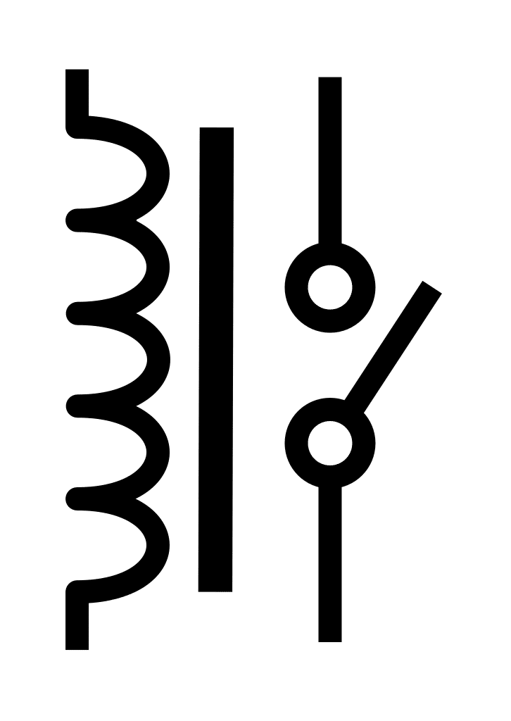
| Normally Open (NO) |
The switch rests in an open (off) state and it is closed (turned on) when the coil is energized. |
| Normally Closed (NC) |
The switch rests in the closed (on) state and it is opened (turned off) when the coil is energized. |
| Latching |
Latching relays have two coils to control the switch, rather than the typical of one. One coil closes the switch and the other coil opens the switch. Once the switch is pulled in one direction, it stays there without the need for continuous current on the coil. This prevents the coil from having to be energized continuously. |
It should be noted that many of the relays available have both normally-open and normally-closed options depending on how it is wired. This detail will be outlined in the part’s datasheet.
How Do I Use A Relay?
A relay is used by wiring the load to be controlled through the switch of the relay and then turning the power to the coil on and off. When choosing a relay, you need to check that the voltage and current ratings of the load are within the specs of the relay. You also need to make sure that you are properly powering the coil to actuate the relay. For example. a relay coil that requires 91mA at 5V cannot be directly driven from a microcontroller that can only supply 40mA. You would need to use a transistor to supply power to the coil.
Something else to consider is that the coil of a relay operates based on the amount of current flowing through it since it is an inductor. The magnetic field generates is a function of current. That means that you can drive a lower voltage coil with a higher voltage as long as you have the appropriate amount of current flowing.
Operating a 3.3V Relay Coil with 12V
A relay has a 3.3V coil with a resistance of 100Ω that needs 33mA to properly operate.
\(\large I = \frac{V}{R} = \frac{3.3V}{100\Omega} = 0.033A\)
In order to operate the coil on a higher voltage (5V, 12V, etc.) we need to add an appropriate amount of resistance so only 33mA of current flow through the coil. If we were operating the coil with 12V we would need to have a total of 364Ω of resistance in the coil circuit to limit the current to 33mA.
\(\large R = \frac{V}{I} = \frac{12V}{0.033A} = 364 \Omega\)
So, we would need to add about 264Ω of resistance in series with the coil.
\(\large \text{Additional Resistance} = R_{total} – R_{coil} = 364 \Omega – 100 \Omega\)
Try It Yourself!
In this example, we’re using 33mA at 3.3V to turn a 1200W (10A, 120VAC) toaster on and off. The heating element in a toaster is correctly simulated by a resistor. Watch how energizing the magnetic coil with the switch pulls the switch in the relay closed. Also, take note of the voltage in the toaster. Even though the toaster is technically off (no current is flowing) the 120VAC wall power is still present in the toaster. This is why you should NEVER stick a metal utensil into a toaster while it is plugged in.
Also, take note of the voltage in the toaster. Even though the toaster is technically off (no current is flowing) the 120VAC wall power is still present in the toaster. This is why you should NEVER stick a metal utensil into a toaster while it is plugged in. I’m sure most toasters disconnect the hot terminal from the coils when it is off, but you never know if the outlet you’re using was wired correctly because it works the same both ways with AC. A really safe toaster would disconnect both sides of the heating element to be sure that no voltage would be present in the elements.