Gustav Kirchhoff was a physicist who defined two laws that are paramount to understanding the behavior of electrical circuits.
Kirchoff’s Current Law (KCL)
Kirchhoff’s first law deals with nodes in a circuit. It says that the algebraic sum of all current entering a node in a circuit is zero. We have to specify that it is the algebraic sum because we must pay attention to the sign (positive or negative) of the current flowing. Current flowing into a node is positive, while current flowing out of a node is negative. This law is very powerful
Now, we have to answer the obvious question, “What is a node?” A node is any point in the circuit where components connect together with wires. This could be ground, the source voltage, or any other tangle of wires connecting components to each other. However, we can apply KCL in a broader fashion by drawing a circle around any portion of our circuit, with or without components, and the sum of the currents in and out of that circle will equal zero.
Alternatively, we can rewrite Kirchhoff’s current law such that the sum of all currents entering a node is equal to the sum of all currents leaving a node. In this form, all currents are represented with positive numbers.
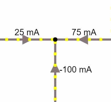
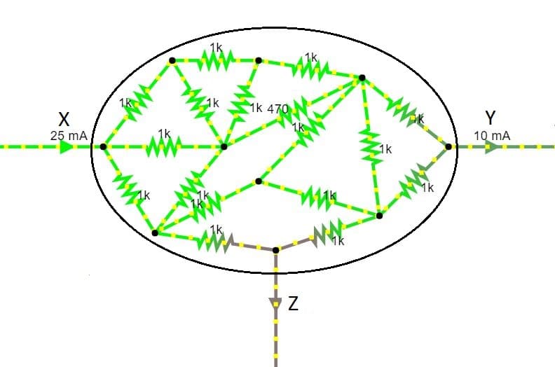
Here we have a daunting (and rather ridiculous) circuit where we would like to know the value of current Z.
This is very easy to do with Kirchhoff’s current law. First, we define the whole mess of resistors as one node (drawing a circle). Now, we define the positive direction of flow on each wire connecting to the node. This is indicated by the arrows. Now, we know that the sum of all of the currents in and out of our node is equal to zero. We write the current balance as follows:
Current X is positive, because it is flowing into the node, while current Y and current Z are negative because they is flowing out of the node. Now, we solve the equation for current Z.
Once we solve for current Z, we find that it is equal to -15mA. The negative value confirms that current Z is flowing out of the node.
Using the Alternate Form of KCL
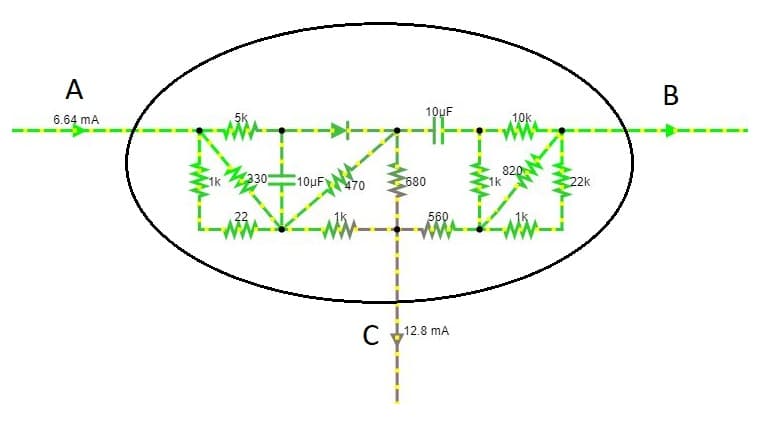
Here is another circuit where we want to do the exact same thing, but this time we will use the alternate form of Kirchhoff’s Current Law, where the sum of all currents into the node are equal to the sum of all currents leaving the node.
The first step is to define the direction of flow in each wire connecting to the circuit that we will call the positive direction. Our definition of positive current flow will follow the arrows on the wires. Now, we add all of the currents flowing into the node on the left side of the equal sign. I this case, that is only current A. And the currents leaving the node are summed on the right side of the equal sign. This balances the current in and out of the node.
In this case, we found current B to be -6.16mA. The negative value just means that our definition of current flow for that wire is backwards. Current B actually flows into the circuit.
Kirchhoff’s Voltage Law (KVL)
Kirchhoff’s second law is the voltage law. It says that the algebraic sum of all voltages around any loop in a circuit equal zero. What this is saying is that if you start at a point in a circuit and sum the voltage increase or decrease of every component as you go around a loop in the circuit, the sum will be equal to zero when you arrive back at your starting point.
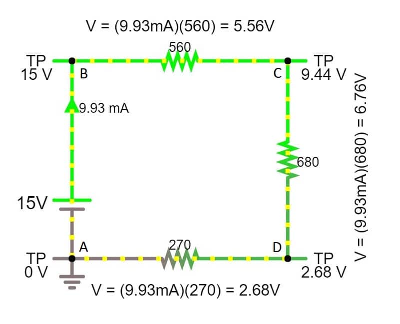
This law is illustrated in the picture above. Starting at point A, we have 0V. As we move from A to B there is a voltage source that adds 15V. Above that is an ammeter, which does not interfere with the circuit. It only reports current, so we will not add or subtract any voltage for the ammeter. Now, at point B, we are at 15V. Moving from B to C, we pass through a resistor. The voltage decreases as the current through the resistor. The voltage decrease is governed by Ohm’s law. Knowing the current and the resistance, we can calculate the voltage drop.
\(\large V = I \cdot R = (9.93mA)(560 \Omega ) = 5.56V\)
Ohm’s law tells us that there is a 5.56V drop across a 560Ω resistor with 9.93mA flowing through it. Now, having lost 5.56V across the resistor, the voltage at point C is 9.44V. Moving from C to D and D to A the current passes through two more resistors. Both of these voltage drops are also calculated with Ohm’s law.
\(\large V = I \cdot R = (9.93mA)(680 \Omega ) = 6.67V\)
\(\large V = I \cdot R = (9.93mA)(270 \Omega ) = 2.68V\)
Using all of these calculations, we can write out the summation for the whole loop. The voltage increases (like the source) are positive, while the voltage drops (like the resistors) are negative.
We can see that this relationship is true, but using it like that is not very useful. What we can do is use it to find the voltage at any point in the circuit with reference to another point in the circuit. Even if we knew nothing about the voltages in this circuit, we could arbitrarily call point A ground (0V). Then we can find the voltage at every other point in the circuit with reference to point A by summing all of the voltage steps and drops along the way. All of these equations begin with the voltage at point A (0V) and then add the voltage increase or decrease of every component in the path point A and the point of interest (B, C, or D).
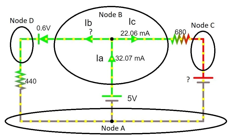
In this example, we have a circuit with some missing values. Using KCL and KVL we can solve for these missing values.
I have started by identifying the nodes in the circuit. For our analysis, we will begin by assuming that the voltage of node A (Va) is 0V. Now, we can begin to solve for the voltage at other nodes. First, we will solve for Vb. If we start at node A, we can get to node B by only passing through the 5V source. So, we start at 0v and the voltage increases by 5V through the source, make Vb equal to 5V.
\(\large Vb = 0V + 5V = 5V\)
Next, we can solve for the voltage of Node C (Vc). Starting at node A, we go up to node B and gain 5V, then the current passes through the 680Ω resistor to get to node C. We can see from the ammeter that there are 22.06mA of current running betwee node B and node C, so we can use Ohm’s law to calculate the voltage drop from the resistor.
This shows us that the voltage at node C is -10V. This means that the voltage at node C is 10V less than the voltage of node A (0V).
Now, we will calculate the voltage at node D. This looks like it will be dificult, since we do not know how much current is flowing through node D, but the voltage drop of a diode is (virtually) unaffected by the amount of current flowing through it. This makes our calculation very easy. Starting at node A and going to node B we gain 5V. Then going from node B to node D the voltage drop 0.6V when it goes through the diode. This makes Vd equal to 4.4V.
\(\large Vd = 0V + 5V – 0.6V = 4.4V\)
Now, we know the voltage at every node, but we don’t know the current flowing through node D (Ib). We can actually calculate Ib in two different ways. The first was is to use KCL. Knowing the values of Ia and Ic we can easily balance the currents in and out of node B to solve for Ib. We know that the current in (Ia) is equal to the currents out (Ib & Ic).
\(\large Ia = Ib + Ic\)
\(\large Ib = Ia – Ic = 32mA – 22mA = 10mA\)
We can also calculate it using Ohm’s law with the voltage of node D and the resistance between node D and node A. We know that the current flowing through the resistor from node D to node A is equal to the voltage different of node D and node A, divided by the resistance.