Intro to Arduino: Analog Input
While digitally reading if a pin is high or low is great, it’s not very helpful with an analog sensor. In this case, we need to know the voltage of the pin. There is a device built into most microcontrollers called an analog-to-digital converter (ADC) that makes this possible. The ADC compares the voltage on the pin with a reference voltage and outputs a value corresponding to the voltage.
Resolution
Inside the ADC, the full voltage range of the ADC is divided into small increments and the input voltage is compared to each incremental voltage to determine its value on the full range. The number of increments depends on the resolution of the ADC. The resolution of an ADC is measured in bits. For example, a 10-bit ADC has 210 – 1 (1023) increments of measurement.
Voltage Reference
The range of measurement of an ADC is between the positive and negative reference voltage (Vref+ and Vref-). For the simplest ADCs, this is from ground (0 V) to the ADC’s source voltage (Vcc). To allow more flexibility, many ADCs today allow you to provide an upper reference (Vref+). This is the purpose of the AREF pin on an Arduino board. If you have an analog input that varies from 0-3V, you do not need your ADC to read the whole voltage range of 0-5V. That wastes your resolution, because 0-3V corresponds to the values 0-614, giving you a resolution of 4.9mV per increment (5V/1023 = 3V/618 = 4.9mV/increment). If you put 3V on the AREF pin and set the ADC reference to external, you will use the full resolution of 1023 increments of an Arduino board from 0-3V. This gives you a finer resolution of 2.9mV per increment (3V/1023 = 2.9mV/increment).
Some fancy ADCs actually let you provide a Vref- which allows you to narrow your measurement range, even more. This further increases the accuracy of the ADC reading.
Arduino IDE
In the Arduino IDE, the ADC is employed with the analogRead() function. This will read an analog voltage on any of the analog input pins.
Reading Analog Pin
To use the function with the default settings, simply call the analogRead() function with the analog pin number as the argument and it will return the value of the voltage of the pin as a numerical value from 0-1023; 1023 being equal to Vcc.
analogValue = analogRead(0); // Read the voltage on A0 and store it in the analogValue variable.Converting the Reading to a Voltage
The reading is then converted into a voltage by multiplying the output by the reference voltage and dividing that by the full ADC output range of 1023.
float voltage;
voltage = (float) (analogValue * 5.0)/1023; // Convert analogValue from ADC to voltage (5.0V reference voltage)
Changing the Reference Voltage
Arduino boards actually have several options for the reference voltage. The input voltage to the MCU is the default reference used. This is typically 5V or 3.3V, depending on your Arduino board. There are also fixed internal reference voltages, depending on the Arduino board that you are using. The Uno board has an internal 1.1V reference, while the Mega board has a 1.1V and a 2.65V reference. Finally, the ADC can also be set to use an external reference voltage on the AREF pin. The voltage supplied to the AREF pin can be anywhere from 0V up to the supply voltage of the MCU. (Never exceed 5v!)
The ADC reference is changed with the command analogReference() with the argument DEFAULT, EXTERNAL, INTERNAL, INTERAL1V1 (Mega Only), or INTERNAL2V56 (Mega Only).
analogReference(INTERNAL); // Sets the Ardunio board to use its internal 1.1V reference for the ADCWhen you change the voltage reference on an Arduino board, it seems to take a while for it to actually switch. The times I have switched the reference I “burn out” the old reference by reading the ADC a lot of times (50 – 150). This seems to work.
analogReference(INTERNAL); // Switch ADC referenceto internal 1.1V reference
for (int i=0;i<100;++i) analogRead(0); // Burn out old ADC refence by reading A0 100 times
ADC Calculations
Here are some useful equations for working with ADCs, where NADC is the value returned from the ADC.
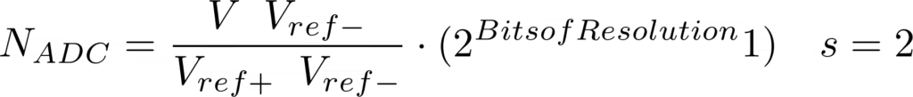


Example Calculations


