Intro to Arduino: Basics of Writing a Sketch (Blinking LED)
While writing a sketch is, or will be, an easy thing to do there are definitely some things that you need to know before you can do it. First of all, be patient. You will get this to work, but you will (99.99% of the time) have problems and you will get frustrated. It may take you hours of troubleshooting, but you will get it to work. Don’t give up.
What Is Computer Programming?
When you write computer code, you are writing a list of instructions. These instructions will be followed from the top to the bottom, line by line. Because we’re trying to talk to a computer, we have to use a language that the computer can understand. Programming languages are like a shorthand language with very specific rules (syntax) for conveying instructions to a computer. The Arduino IDE (Integrated Development Environment) uses the programming language C++. It is a very powerful language that is pretty easy to learn. While there is a lot to learn about using C++, the fastest way to start is to jump in.
Structure of a Sketch
An Arduino sketch has two main parts; the setup() and the loop(). All you really need to know right now is that setup() runs first and it is run only once. Then loop() runs and re-runs forever.
// Sketch starts here

void setup() {
   // Code here runs one time before loop()
}

void loop() {
   // Code here repeats forever
}

// Never gets here because of the infinite loop
Some Example Code
Here is a bit of code for us to chew on. You will notice the comments in this code. Comments are a very powerful tool because they allow you to add normal text to explain what is happening and the computer ignores them. In C++, comments are defined in two ways. A // makes the rest of the current line a comment and all of the text between the /* and the */ tags is a comment.
// Sketch starts here

byte VariableA; // Creates a variable of the type 'byte'
/*
A variable is a defined spot in memory that we will
reference with the name that it was just given (VariableA).
Variables can be different sizes. This variable is a
type byte. A byte is 8 bits of memory which can hold a
maximum value of value of 2^8 - 1 or 255. If we try to
count to 256 the variable will overflow and be back at 0.
*/

void setup() {
   // This code runs one time before loop()
   VariableA = 0; // Sets VariableA equal to 0
}

void loop() {
   // This code repeats forever
   VariableA = VariableA + 1; // Add 1 to VariableA
}

 // Never gets here because of the infinite loop
In this sketch, a 1 byte (8 bit) variable is defined; VariableA. In the setup, VariableA is set equal to 0. Then, in the loop, VariableA in incremented (increased by 1) every time the loop is executed. This will go on forever. When this program is run, VariableA will be created, but we won’t know its value for sure until it is set equal to 0. Then, when the loop starts executing, VariableA will be equal to 1, then 2, then 3, and so on, all of the way to 255. Next, VariableA will be incremented again and its value will roll over from 255 (11111111 in binary) to 0 (00000000 in binary). After that, it will just continue incrementing. This simple sketch loops infinitely, counting from 0 to 255 in VariableA.
The only purpose of this sketch is to give you a small taste of programming. It is entirely useless because it does not interact with the world. It does not output anything to a screen or control any electronics and it does not take any inputs, but hopefully, it does demonstrate some of the basics of programming.
Blinking an LED
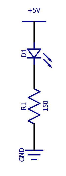
Now, let’s take a look at a real sketch. This sketch blinks an LED, which is an excellent example of a microcontroller affecting the circuitry around it. For this sketch, an LED is connected to one of the digital input/output pins of the development board. Most Arduino boards already have an LED connected to pin 13, but we can add another one too. To add an LED connect its anode (+) to pin 13 of your Arduino board. Then connect the LED’s cathode (-) to a resistor (150 – 1000Ω). Finally, connect the other side of the resistor to ground (0V).
Once we have an LED connected, we can get to the code! Here is the whole program.
// Sketch starts here

// setup() runs one time before loop()
void setup() {
   pinMode(13, OUTPUT); // Set digital pin 13 to output
}

// loop() runs forever
void loop() {
   digitalWrite(13, HIGH); // Switch pin 13 output to high voltage (5V) - Turns LED ON
   delay(1000); // Wait 1000ms (1s)
   digitalWrite(13, LOW); // Switch pin 13 output to low voltage (0V) - Turns LED OFF
   delay(1000); // Wait 1000ms (1s)
}

// Never gets here
Let’s go through this step by step.
// setup() runs one time before loop()
void setup() {
   pinMode(13, OUTPUT); // Set digital pin 13 to output
}
The first thing we do is in the setup(). We change the mode of pin 13 to be an output. All of the pins on an Arduino board (0-13 & A0-A5) can be used as an input or an output. When a pin is set as an input, the microcontroller connects to the pin with a very high resistance, so that it does not interfere with the circuit. Current does not flow in or out of the microcontroller. When a pin is set as an output, the pin is connected directly to Vcc (HIGH) or GND (LOW) and current is allowed to flow freely. As an output, pin 13 is able to source current to the LED.
Next, the code enters loop(). This is where we blink the LED.
void loop() {
   digitalWrite(13, HIGH); // Switch pin 13 output to high voltage (5V)
   delay(1000); // Wait 1000ms (1s)
   digitalWrite(13, LOW); // Switch pin 13 output to low voltage (0V)
   delay(1000); // Wait 1000ms (1s)
}
First, we set pin 13 to a HIGH output state. This connects pin 13 to Vcc (5V in most cases). Now current will flow from 5V, through pin 13, through the LED and resistor, and then to ground.
Next, we have to tell the microcontroller to wait. This is because the microcontroller works so quickly it can turn the LED on and off faster than you could see it. In this example, we want the LED to turn on for one second and then off for one second. So, we use the function delay() with the argument 1000 which instructs it to wait 1000 milliseconds, which is equal to one second.
After one second, the microcontroller moves to the next line of code where pin 13 is set LOW. When pin 13 is low, it is connected to ground and current will not flow from ground, through the LED, and back to ground. So, this effectively turns the LED off. Then we add another delay so that the LED is off for a whole second. Finally, the whole loop repeats to continue blinking the LED, forever.
Resources
To learn more about the basics of getting started with Arduino development boards, take a look at these links. The Arduino Language Reference is particularly helpful.
- Getting Started with Arduino and Genuino Products – Arduino.cc
- Arduino Language Reference – Arduino.cc
Try It Yourself
Copy the code above and paste it into the Arduino IDE. Now, click upload. The pin 13 LED should start blinking!
Now, mess around with the code. Change the length of the delay. Make it blink three times fast and then wait before blinking three times again. Do whatever you want! The point is of this exercise is to get comfortable changing the code and making it do what you want it to do.