Intro to Arduino: Digital Input and Output (I/O)
Digital input and output is one of the most basic operations of a microcontroller. All of the pins on an Arduino board (0-13 & A0-A5) can be used as digital inputs or outputs in addition to any other function (e.g. analog input) connected to the pin.
Digital Input
When we talk about digital input, we are talking about sensing when a pin is at high voltage or low voltage. High or low is usually referenced against half of the supply voltage of the microcontroller (Usually 5V/2 = 2.5V). If the voltage of the pin is above Vcc/2, the pin is considered to be high.

Arduino IDE
In the Arduino IDE, you can read the state of a pin by using the function digitalRead(). The function digitalRead() accepts one argument, the number of the pin to be read (0-13 or A0-A5), and it returns the state of the pin as a 1 (HIGH) or 0 (LOW).
The digital state of a pin can be read whether or not it is set as an input. However, when you read the state of a pin that is set to output, you will just be reading the defined output state.
int pinState; // Create variable (integeer has a size of 2 bytes or 16 bits)
pinState = digitalRead(2); // Reads the state of pin 2 and sets pinState equal to the result (1 or 0)
Pull Resistor
When a pin is set as an input it has a high impedance (resistance to the flow of electricity), meaning that the voltage of the pin is not affected by the microcontroller. It is only affected by the circuit that connects to it. If the circuit is disconnected from the pin (e.g. by a switch) we can not be sure what state we will read from the pin. It may read LOW or static charge on the pin might make it read HIGH. In this case, the pin is said to be floating. This is why it is important to always have a pull-up or pull-down resistor connected to an input pin. This is a resistor that connects from the input pin to high voltage or ground. This ensures that when the switch is open, the pin will be pulled HIGH or LOW.
Digital Output – Tristate
States 1 & 2: HIGH and LOW
The output mode is intended to affect the circuit it is connected to. In output mode, current can freely flow into or out of the pins on the microcontroller and it can be switched HIGH or LOW. When an output pin is HIGH, it is connected to the MCU supply voltage (usually 5V). When the pin is LOW, it is connected to GND. As an output, current can always flow in or out through the pin but it will only flow if there is a potential difference (high voltage to low voltage) between the pin and the circuit. If the pin wires to an LED and resistor, and then to ground, current will only flow if the output pin is set to high voltage. If the output is set LOW both sides of the resistor will be at the same potential and no current will flow. (Tip: The flow of current will also stop if both sides are connected to high voltage.)

The digital outputs of the Atmel MCUs used in Arduino boards are able to source or sink up to 40mA on a single pin. This is plenty to power devices like LEDs.
In the Arduino IDE, output pins are switched HIGH and LOW using the digitalWrite() command. The digitalWrite() command accepts two arguments: the pin number to switch (0-13 or A0-A5) and the state it should switch to (HIGH or LOW).
digitalWrite(13, HIGH); // Switch pin 13 to HIGH stateState 3: High Impedance
Ironically, the third output state is input. Sometimes the output state that you need is not HIGH or LOW, but rather to not affect the circuit at all. This is very common when communicating with other devices. The other device needs to be able to pull the wire HIGH or LOW and not be affected by the output of your microcontroller. In this case, you actually change the pinMode() of the output pin to input, which makes it high impedance (no current can flow).
Pin Mode: Input or Output
In the Arduino IDE, the mode of a pin is set with the function pinMode(). The pinMode() function accepts two arguments: the pin whose mode to change and the mode it which it will change. The pin mode on any microcontroller can be set to OUTPUT or INPUT, while the Atmel processors used in Arduino boards actually have a third mode. The third mode is INPUT_PULLUP. This sets the pin to a high impedance, input state, but it also engages a weak (~19kΩ) pull-up resistor on the pin. This is very useful when connecting a switch because you can use this internal pull-up rather than an external pull-up resistor.
Something to remember is that the mode of a pin can be changed at any point in your program (not just in setup) and as often as you want. This is very helpful with communications, where you need to output on a wire and “listen” for a response on the same wire.
pinMode(13, OUTPUT); // Set pin 13 to output mode
pinMode(2, INPUT); // Set pin 2 to input mode with no pullup
pinMode(3, INPUT_PULLUP); // Set pin 3 to input mode with pullup
Example
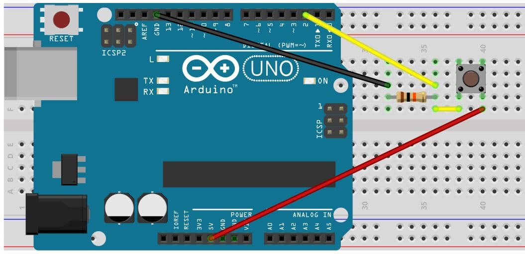
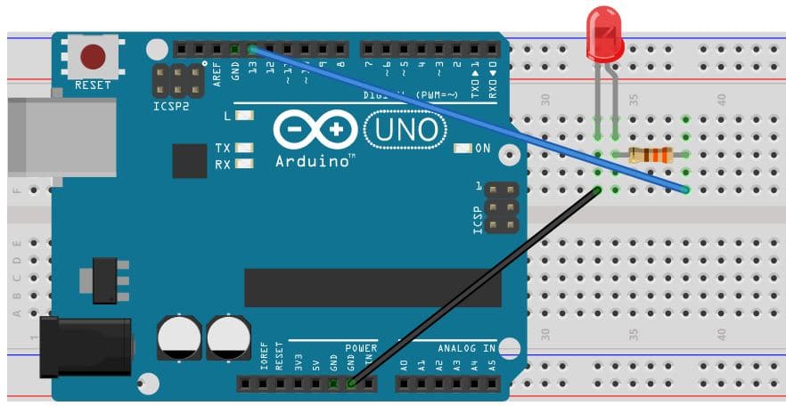
This example code is intended to be run on an Arduino board with the circuits shown above. The switch is wired to pin 2. Pin 2 has a pull-down resistor and the switch connects the pin to 5V. The LED is wired to pin 13. This is actually not necessary for this example because every Arduino board has a built-in LED that is connected to pin 13. You can use this instead.
Build the switch circuit, upload this code, and give it a try!
int button; // Define a global variable (can be used by any function) for the state of the button input

void setup() {
   pinMode(13, OUTPUT); // Set pin 13 to output mode
   pinMode(2, INPUT); // Set pin 2 to input mode

   digitalWrite(13, LOW); // Make sure the LED is turned off to begin with
}

void loop() {
   button = digitalRead(2);

   // If the button is being pushed, turn on the LED
   if (button == 1) {
      digitalWrite(13, HIGH);
   }
   else // If the button is not being pushed, turn off the LED
   {
      digitalWrite(13, LOW);
   }
}